ESP32 S3 DevKitC 1 Multiple Sliders
|
Nederlandstalig Bij het ontwikkelen van dit programma voor de ESP 32 is uitgegaan van de software en de toelichting van Rui en Sara Santos die zij hebben gegeven op https://RandomNerdTutorials.com/esp32-web-server-websocket-sliders. Sommige noodzakelijke instellingen worden door hun toegelicht in de beschrijving. Het is aan te bevelen eerst hun voorbeelden werkend te krijgen en daarna pas de uitgebreidere versie die hier gepresenteerd wordt te testen. |
|
English language by Google Translate This program for the ESP 32 was developed based on the software and the explanations of Rui and Sara Santos that they provided at https://RandomNerdTutorials.com/esp32-web-server-websocket-sliders. Some necessary settings are explained by them in the description. It is recommended to get their examples working first and then test the more extensive version presented here. |
|
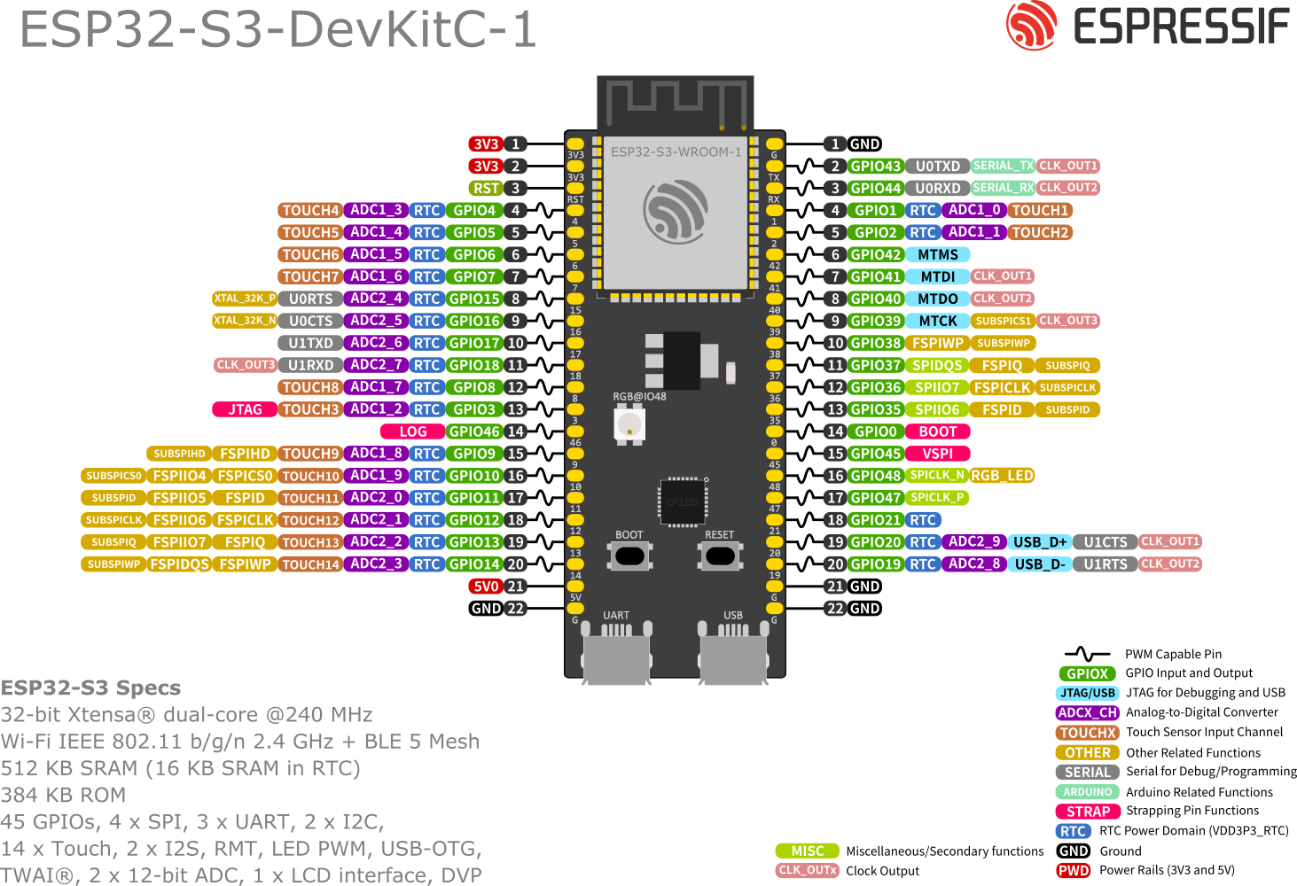
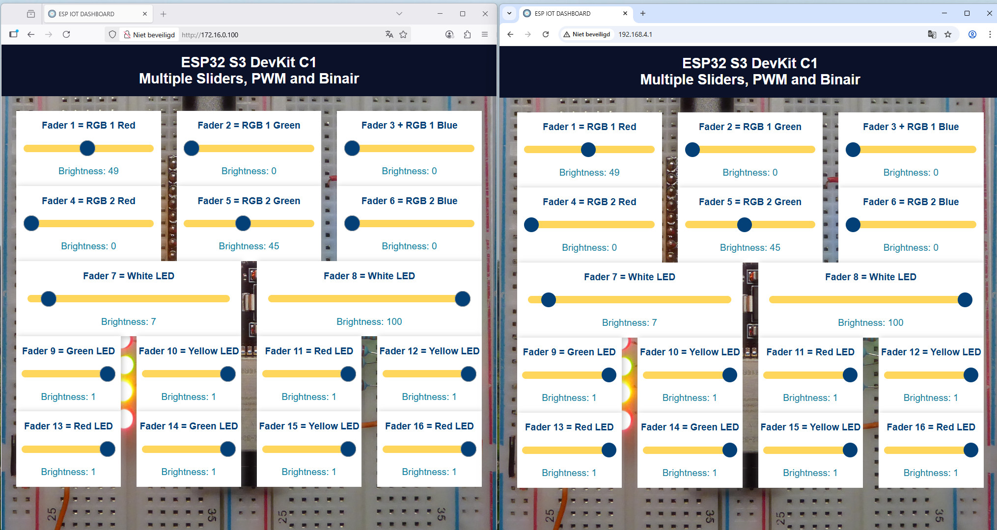
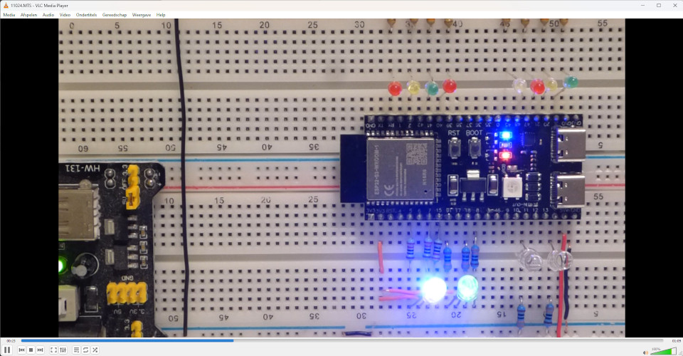
Korte beschrijving: Als basis voor dit experiment is gebruik gemaakt van de ESP32 S3 DevKitC 1 N16R8. Deze module heeft twee USB type C aansluitingen voor de stroomvoorziening en de programmering. De microcontroller is een ESP32 S3. De USB-aansluiting is type C, om de software te laden is het niet nodig om de knop Boot in te drukken. De ESP32 S3 heeft slechts 8 PWM kanalen, in tegenstelling tot de originele ESP32, die heeft 16 PWM kanalen. De schuifregelaars 1 tot en met 8 gebruiken de PWM kanalen 0 tot en met 7, hebben een schuifbereik van 0 tot 100 en de PWM kanalen hebben een bereik van 0 tot 255. De schuifregelaars 9 tot en met 16 hebben een bereik van 0 tot 1, kunnen zodoende alleen geheel uit of vol aan en de bijbehorende LED's worden digitaal aangestuurd. De gebruikte poorten zijn met proberen (try-and-error) opgezocht, want niet alle poorten kunnen als uitgang gebruikt worden. Als de poorten 35 t/m 39 als uitgang aangestuurd worden gaat de SOC continu rebooten. Poort 45 werkt op mijn exemplaar ook niet als uitgang. Poort 48 kan gebruikt worden om de RGB-Led aan te sturen, maar daarvoor moet een druppel soldeer op de twee puntjes naast die RGB-Led gesoldeerd worden. Ik heb geen soldeerbout met zo'n fijne punt. Trouwens, op sommige versies met de ESP32 S3 is die RGB-Led aangesloten op poort 38. Het bord heeft een rode led om te zien of het onder spanning staat. Deze led is niet aan te sturen. Ik heb deze versie zo eenvoudig mogelijk gehouden, dus één vaste frequentie voor alle kanalen en géén tweede sliders met een logaritmische verdeling van de pulsduur. |
|
Short description: The ESP32 S3 DevKit C1 N16R8 served as the basis for this experiment. This module has two USB Type-C connectors for power and programming. The microcontroller is an ESP32 S3. The USB connector is Type-C; pressing the Boot button to load the software is not necessary. The ESP32 S3 has only 8 PWM channels, unlike the original ESP32, which has 16 PWM channels. Sliders 1 through 8 use PWM channels 0 through 7, with a slider range of 0 to 100, and the PWM channels have a range of 0 to 255. Sliders 9 through 16 have a range of 0 to 1, so they can only be switched fully off or fully on, and the corresponding LEDs are controlled digitally. The ports used were determined through trial and error, because not all ports can be used as outputs. If ports 35 through 39 are controlled as outputs, the SOC reboots continuously. Port 45 doesn't work as an output on my sample either. Port 48 can be used to control the RGB LED, but that requires a drop of solder to be soldered to the two dots next to the RGB LED. I don't have a soldering iron with such a fine tip. By the way, on some versions with the ESP32 S3, the RGB LED is connected to port 38. The board has a red LED to indicate power. This LED cannot be controlled. I kept this version as simple as possible, so one fixed frequency for all channels and no second sliders, with a logarithmic distribution of the pulse width. |
|
Links IP=172.16.0.100 van de ESP32 als Station Rechts IP=192.168.4.1 van de ESP32 als Access Point |
|
On the left IP=172.16.0.28 of the ESP32 as Station On the right IP=192.168.4.1 of the ESP32 as Access Point |
|
|
|
|
|
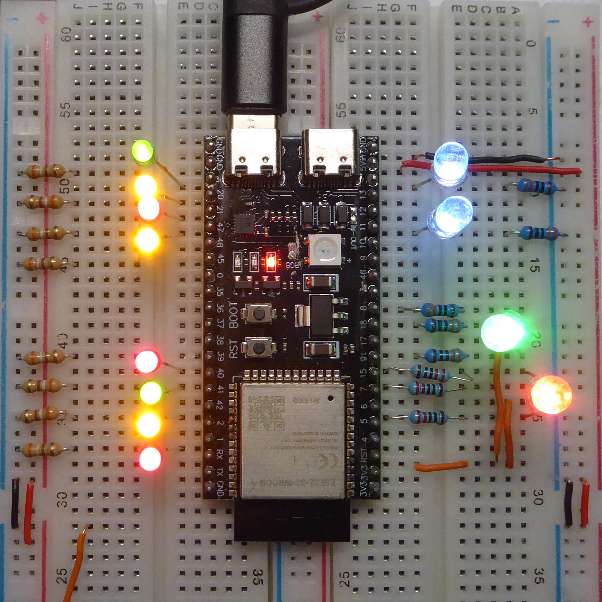
Schuifregelaars 1, 2 en 3 èn 4, 5 en 6 zijn elk via een weerstand van 330 ohm gekoppeld aan respectievelijk de rode, groene en blauwe led van een RGB Led met gemeenschappelijke anode. Om de gewenste kleur te krijgen moet wat geschoven worden met de sliders, groen is nogal overheersend voor het menselijk oog. Een kleur geel is te krijgen met 100% rood, ca 40% geel en 0% blauw. Schuifregelaars 7 en 8 zijn witte led's, elk aangesloten met de anode aan de poort en de kathode via een weerstand van 330 Ohm aan 0 volt. Schuifregelaars 9 tot en met 16, zijn rode, gele en groene Led's, die met de anode aan de poort en de kathode via een weerstand van 390 ohm aan 0 volt zijn aangesloten. De helderheid van de groene Led's valt wat tegen |
|
Sliders 1, 2, and 3, and 4, 5, and 6 are each connected via a 330 ohm resistor to the red, green, and blue LEDs of an RGB LED with a common anode, respectively. To achieve the desired color, the sliders must be adjusted slightly, as green is quite dominant to the human eye. Yellow can be achieved with 100% red, approximately 40% yellow, and 0% blue. Sliders 7 and 8 are white LEDs, each connected with the anode to the gate and the cathode via a 330 ohm resistor to 0 volts. Sliders 9 through 16 are red, yellow, and green LEDs, each connected with the anode to the gate and the cathode via a 390 ohm resistor to 0 volts. The brightness of the green LEDs is a bit disappointing |
|
|
|
|